
May 12th
Modeling, Moderate, Product design, Tutorials
This article has been viewed 163643 times. You can leave a response, or trackback from your own site.

Modeling a Desk Lamp


STEP 2
In this step, we will be modeling the semi-sphere part.
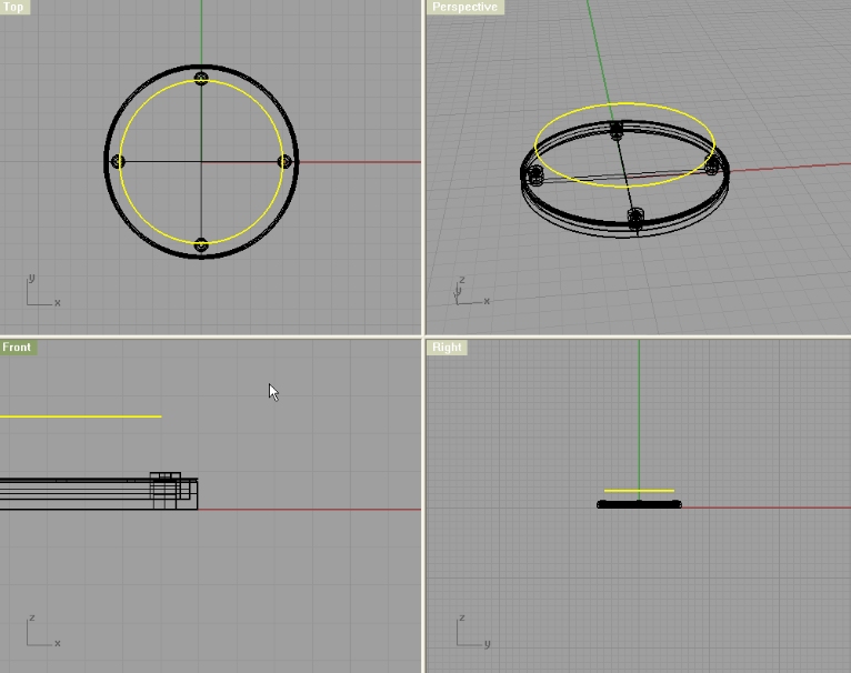
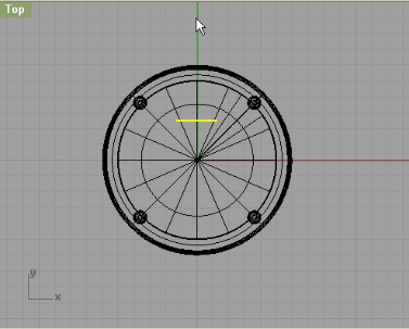
So, in the top viewport, make a circle 10cm in diameter, and move it up (from front viewport by 2.45cm):
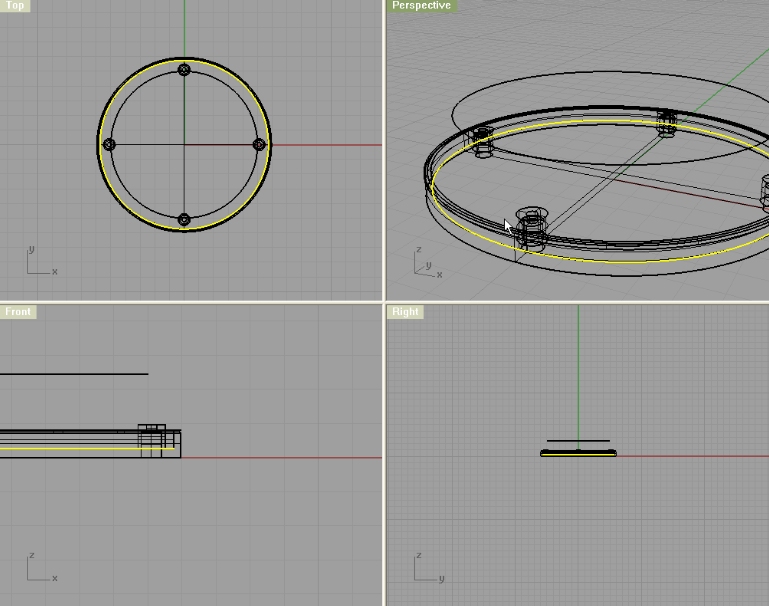
Select the inner lower circle, and extrude it with 1.5cm as distance:
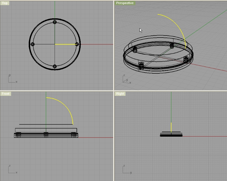
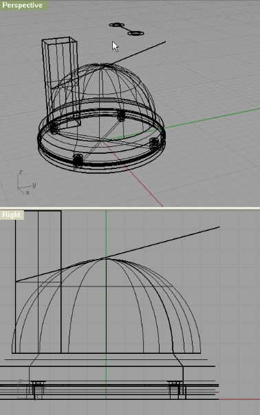
Now, make an arc starting from the center of 10cm circle so it is 5cm in radius:
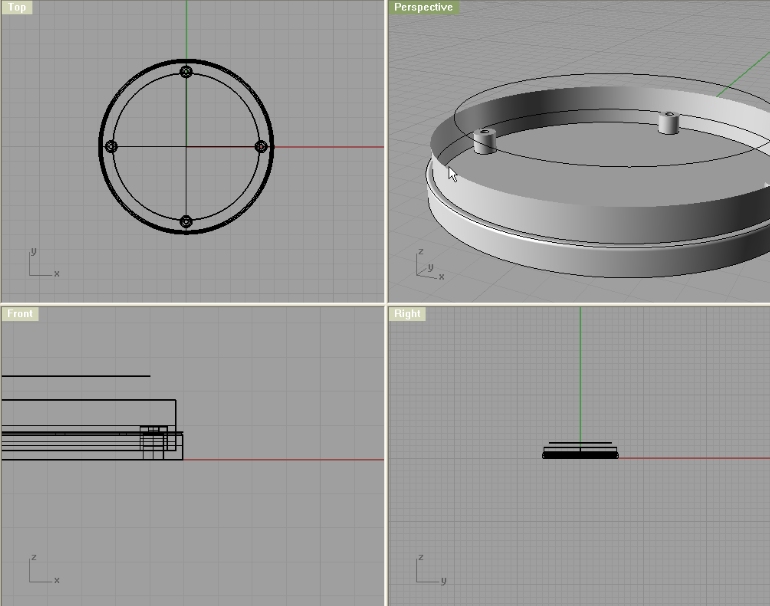
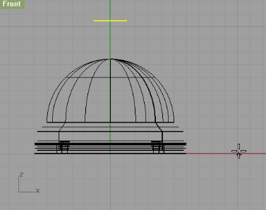
Using Sweep1 make a surface with arc as cross section curve, and circle as rail. Then, using Loft create a surface between selected circles in the image below:
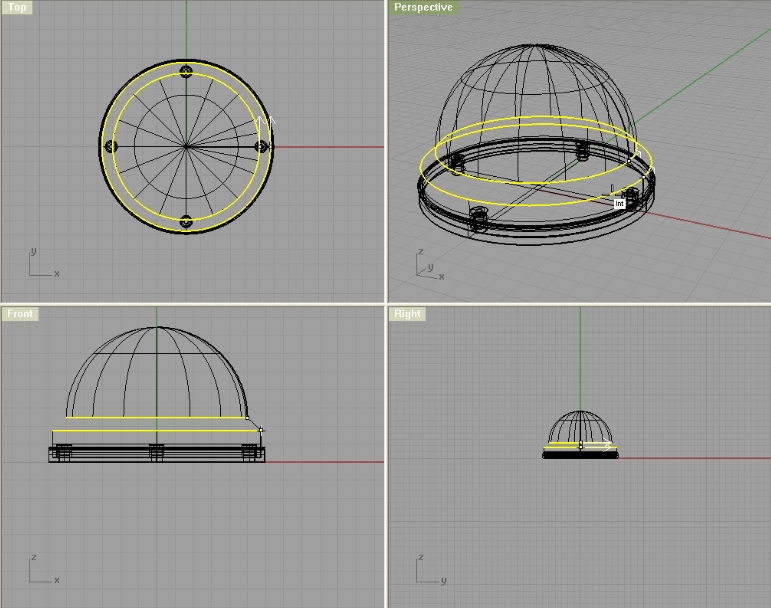
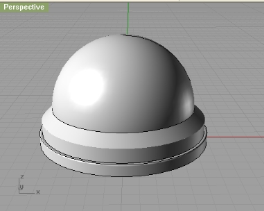
You should have this:
Now, we need to rotate everything by 45 degrees because the bosses are actually positioned that way. And since we don’t want to model everything under 45 degrees, we will just simply rotate this.
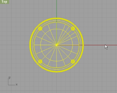
Now, that we rotated everything, we will start modeling the switch and other details.
We first need a line 2.6cm long. You can make it anywhere in the top viewport. Then we will move it to the center of our semi-spher (use Mid and End osnap options).
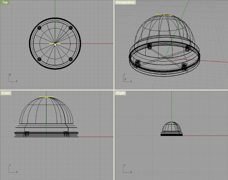
Then move that line up (from top viewport) by 2.5cm. That line is telling us how far the centres of tubes for the chrome lines are. If you know what I mean 😀
You can drag that line up (from front viewport). Don’t drag too little, as wee need enough of the tubes so we can trim off some of them later.
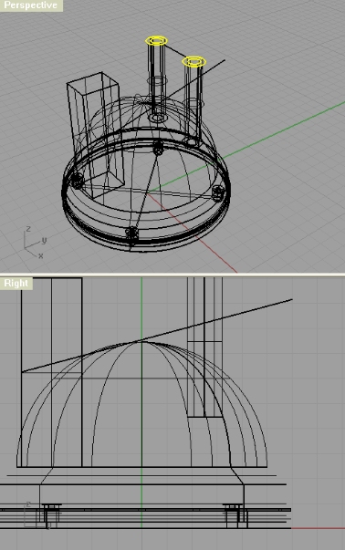
Next, create two circles, one with 0.8cm diameter and the other one 1.4cm diameter. Make them concentric. Move them so the bigger one is touching the right end of the line we previously made.
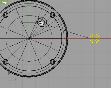
Now, mirror those two circles over the Mid point of your line so you get one more group of circles on the other end of the line.
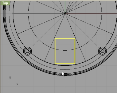
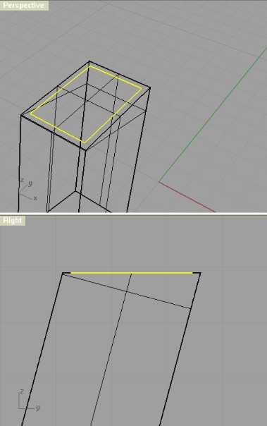
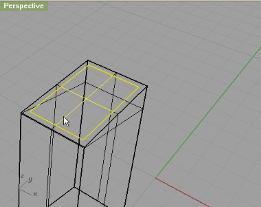
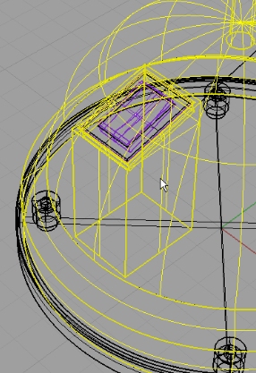
Ok, lets get you confused even more. Leave those circles now (we’ll get back to them) and make a Rectangle and make it 1.9cm x 2.4cm. And position it using Quad option in Osnap on the quad point of your semi-sphere:
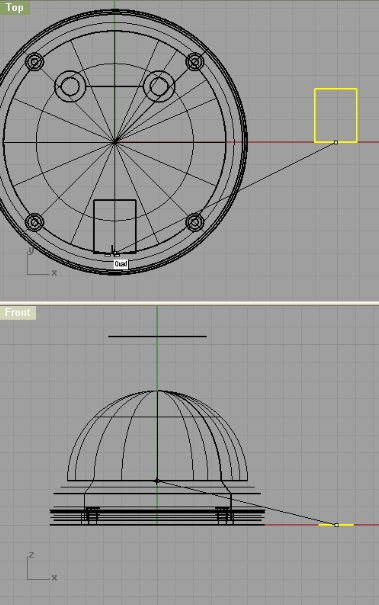
Now we need that rectangle moved up (from top viewport) by 0.2cm. So, move it.
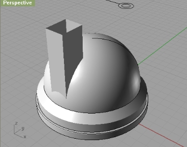
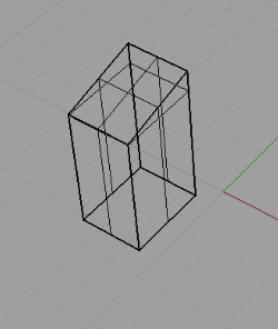
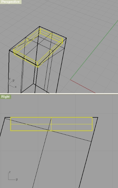
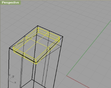
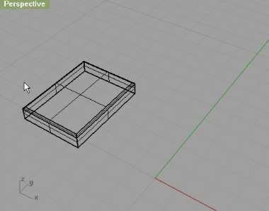
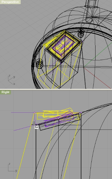
Now that we positioned our rectangle right, we can now extrude it. Just make it high enough so you get something like on the image below:
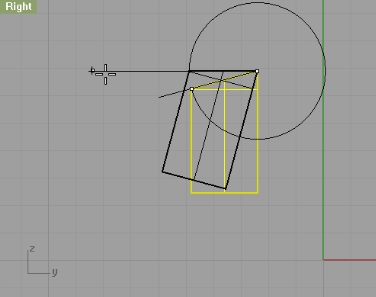
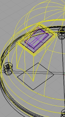
Lets create a line 3.8cm long on the edge of our extruded rectangle (use End and Near options in Osnap for easier alignment):
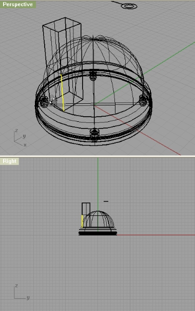
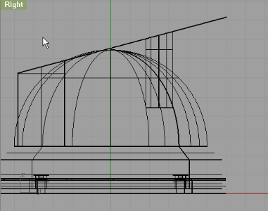
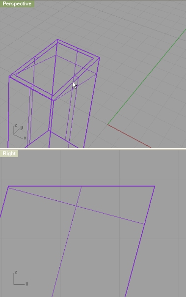
Now, from right viewport, we will rotate that line for exactly 105 degrees.
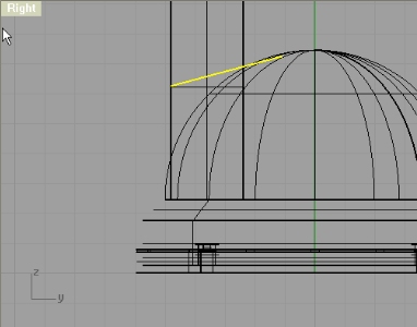
Using Extend command we will extend that line just enough so it passes 4 circles we made earlier.
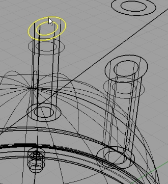
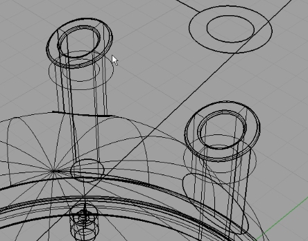
Ok, lets get back to our circles. Select all 4 and extrude them so they go through the semi-sphere.
Now, we will use that extended line to trim off the extra parts on the extruded rectangle and 4 extruded circles (trim from Right viewport)
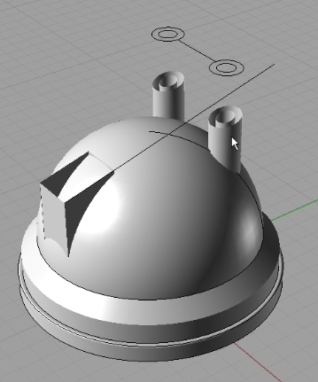
With PlanarSrf cap the tubes:
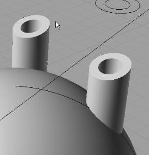
Now, using the same method, cap the rectangle. Just, select 4 edges, and with PlanarSrf cap it.
Join caps with other corresponding surfaces.
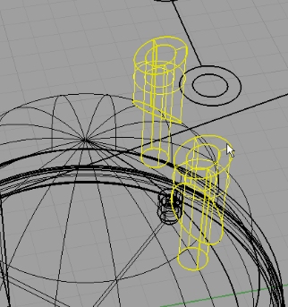
Trim two tubes and semi-sphere. This might be a little hard to explain, but I’ll give it a try. For each tube we have inner and outher surface. We need to trim off the outer surface with semi-sphere, so we will get holes on the semi-sphere and trimmed tubes. This is just a preparation for creating the shell which I will not create in this tutorial. The method is pretty the same as in other tutorials that have explained shelling (i.e. Modeling Rowenta hair dryer)
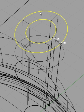
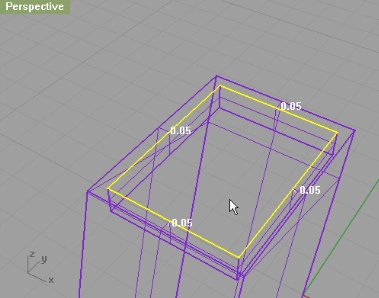
Next, we will fillet the edges of those tubes. Using FilletEdge, select 4 edges (2 for each tube) and with 0.05cm as radius fillet the edges:
Now, isolate the rectangle part (just hide everything else or put everything in other layer, and hide the layer)
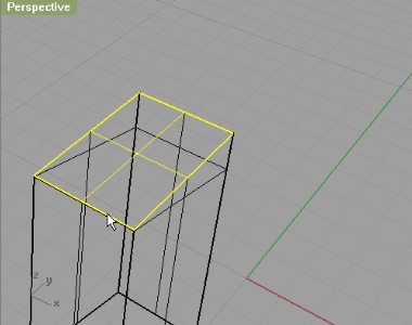
We need to rotate it so the upper surface is flat:
Since this is Joined surface we first need to input the DupFaceBorder command, and then select upper surface, so we can get a fine rectangle out of its edges:
Now that we have that rectangle, we will offset it with 0.15cm.
Next, using Split command split the surface with offset rectangle.
Now, select that offset rectangle, and extrude it down just a little:
Now we need two of these extruded surfaces. You can either copy it using copy command, or you can copy it to Clipboard using Edit->Copy (CTRL+C) and then Paste it using Edit->Paste (CTRL+V) OR you do it like I do 😀
First, we will copy it using CTRL+C, and make sure in the meantime you don’t copy anything else in the clipboard as you will erase the copied data (our surface). While we have that surface in our clipboard, we will continue with the same surface we have copied:
Select it, and select upper rectangle surface and Join that:
Using filletedge, fillet 4 edges with 0.05cm. (I have put that in a separate layer, and hidden the rest)
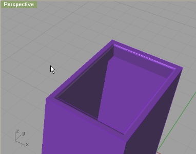
Now, hide this, and show other:
Now, remember that copied surface? Well, paste it now with CTRL+P. That surface needs to be joined with other (purple) surface. Again, using filletedge fillet the 4 edges with 0.05cm:
Now, using that already offset rectangle, we will make another offset. This time we will offset it by 0.3cm.
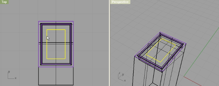
We will use this just as a reference for the switch button, so we will move it a bit up (from the right viewport):
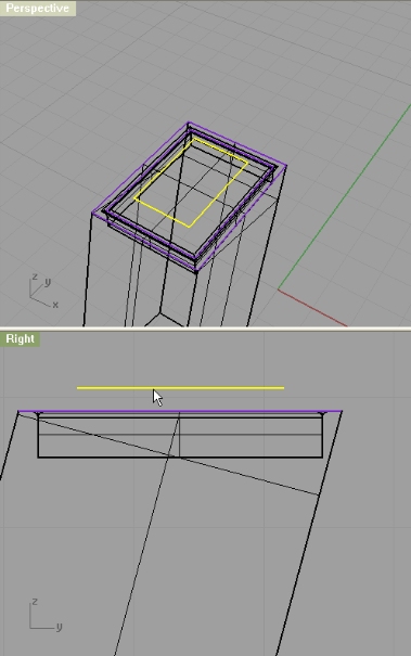
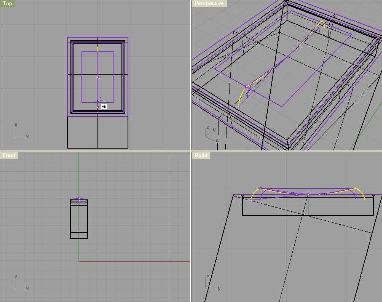
Using SmartTrack, we will make a Point in center of rectangle:
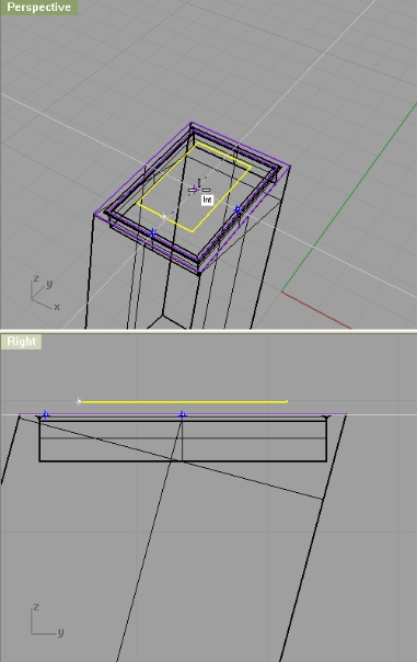
Using that Point and two Mid points we will create a curve (InterpCrv) starting from one Mid, over Point and ending in opposite Mid point.
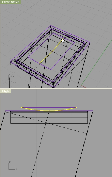
Create an interpcrv from one end of our curve, Intersecting it with surface (just two points, so at first it looks like a line - but when we turn the Control Points on, you’ll see it is actually a curve)
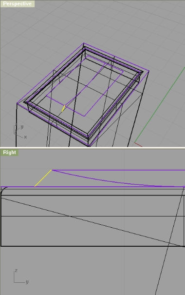
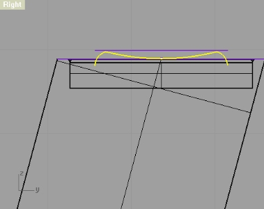
Now, turn on the control points (PointsOn) and edit the curve from right viewport (make sure your osnap settings don’t get in a way - you can disable osnap temporarily)
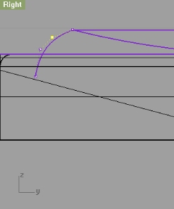
Don’t forget to turn the control points off (PointsOff) if you want to move or do anything else with your curve). Ok, once we done that, we will mirror that curve, so we have one on the other end too.
Now, select and join three curves we made:
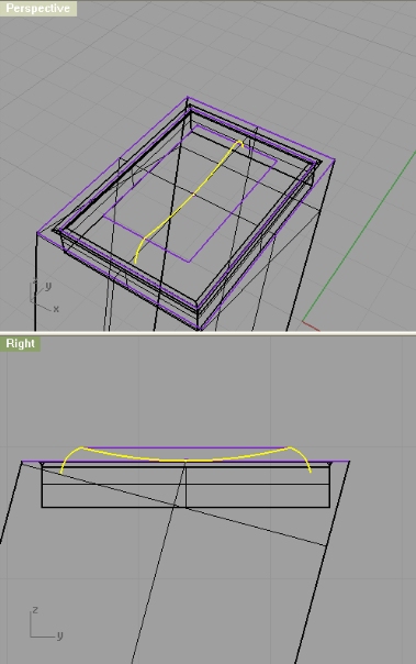
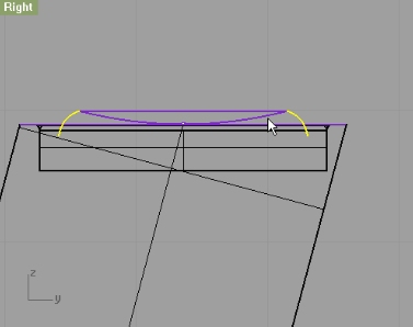
Ok, now we will scale this curve a little. You see where small curve and bigger curve connect with mid points of rectangle. Well, this is how we made it, but we need our ends of curve be there:
I have started a Scale command from the center of curve, and then clicked on the end of our curve, and when you move it scales, so from top viewport, click on the Mid point of rectangle.
Make a line between two ends of this curve (or you can simply close that curve CloseCrv- the same result but less work)
Now, turn on the Control Points (PointsOn) and move the bottom part down a bit:
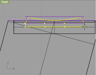
Turn off the Points (PointsOff). Now you can move the whole closed curve up a bit and finally extrude it (use cap). Make sure your BothSides is set to Yes. If your Near option in Osnap is on, then you should simply click on the Near part when you see that the extrusion distance meets the rectangle width. We need to rotate it a bit, so it looks like the lamp is off:
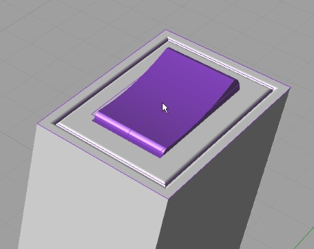
We need to rotate the whole switch group back. Hopefully you left your line (the one we extended) so we have a reference point of rotation.
Next we need to trim the rectangle surface with semi-sphere surface:


Congratulations!
I like your side, news, video tutorials…etc. But in tutorials I would include also .pdf tutorial on the end (it is much easier to read and to see the pictures).
Keep with good work!
Best regards,
uros
well thanks. I’ll think about pdf, if theres a good and fast solution to creating pdfs then fine 😉
thanks, I just hope few more ppl would find my efforts worth and help me out with writing tutorials, so I can learn something too 😉
hey thanks alot for ur tutorials i reallyyy learned alot. but i just want to ask u a tinny favor …iz it possible to put the photos little bit big size. i know if i ckick i can see big size but when iam printing they became small:((( sorrri to asked alot
Thanks a Lot Dude! It was very joyful
Its impressive the way you make your tutorials… so detailed
thanks for your tuts!!!!
great rhino tutorial, especially the shelling. i have a question: in a few places (e.g. third step on page 4) you do a trim that also seem to create fill surfaces. e.g. when you trim the three extruded rectangles through the shelled lamp head, you appear to be getting a solid result. When I do it, I have to creat the vertical fill surfaces by hand. Is this something you’re leaving out, or am I misunderstanding?
thanks again, these are the best notes i’ve ever seen. i’d love to see pics & text of how you set them up, & how you measure the object for the modeling.
well, since we are extruding those three rectangles, and trimming the extruded surfaces with the shell, I suppose either you are doing something wrong, or you did something wrong 😉 but keep trying
Whenever I *trim* a solid with another entity (curve, surface, or solid) the result never seems to be closed; only if I do a *boolean subtract* is the result closed. E.g. make a cube and trim out a hole with an extruded circle: there will be two circular holes in the cube’s faces, but no interior cylindrical wall. If you send me an email address I’ll send you pictures of what I mean. But I really *want* it to work like you say! Thanks for any explanation…
Bad Ass! Learned a lot during this tutorial!
Oh, wait, I see what you’re saying: trim A to B then trim B to A and join…right?
well, boolean operations work actually the same as trim and join, but you do it in one step and one command and sometimes avoid unnecessary problems. I am just too much used to trim so I often forget to use boolean 😀
teach me to know more about rhino.
It would be nice if the blueprints weren’t in pdf… ya know so you could actually use it maybe.. just a thought. It would be much easier to make the body shapes using profile curves from a bitmap but you can’t get a bitmap.
your tuts suck. I could getter better tuts from a retarded aspergers baby
You can look up on vector graphics on wikipedia if you can’t grasp how vector is more powerful than raster. http://en.wikipedia.org/wiki/Vector_graphics
And in case you didn’t know, you can export pdf-s into jpeg images which then you can insert into Rhino.
With a little more “advanced” rocket science, you can actually import vector graphics as curves into Rhino, which is another reason why I provide vectors.
Good tutorials - thanks! I agree with the presentation though - it´s difficult to keep flipping betweeen instructions and the images for clarification. Maybe you could use a plugin like Simpleviewer so that when you click on the image, it is overlaid over the current page at a large size.
another good tutorial!! thanks a lot again. but this time I had so much trouble with triming two surfaces in the 4th step. I can not trim just with one click, I mean after first trim there is still surfaces that I have to click on to continue triming. is it the only way or am I making a mistake? please give us some tips about triming…
Great tutorial.
You can view my render in the forum 🙂
Nice tutorial…:) Is there something like video of this?:)
Do you know if Rhino for OSX has the PlanarSrf command at this point. I am a newbie and cannot connect the surfaces making up the small circle to the big in part ten of step 1
Great tutotial.
I can really use some steps for my next project, on which I now was stuck.
Do you have also vids on YouTube?
Best regards Paul
what is Rhino OS X
Is this a 3d software